Propulsion and hull integration
The integration of propulsion and hull is crucial for obtaining high efficiency, reducing pressure pulses and improving interaction effects.
CFD can be used efficiently in propeller/hull integration to optimise performance.
Examples of studies:
- Bare hull or self-propulsion simulations using virtual propeller model or sliding mesh technique with the real propeller geometry to predict propeller/hull interaction effects and optimise propulsive system performance.
- Evaluation and/or optimisation of headbox and appendage designs.
- Analysis and optimisation of propeller rotational direction, neutral rudder angles (toe in/out) or thruster orientation (tilt and toe in/out).
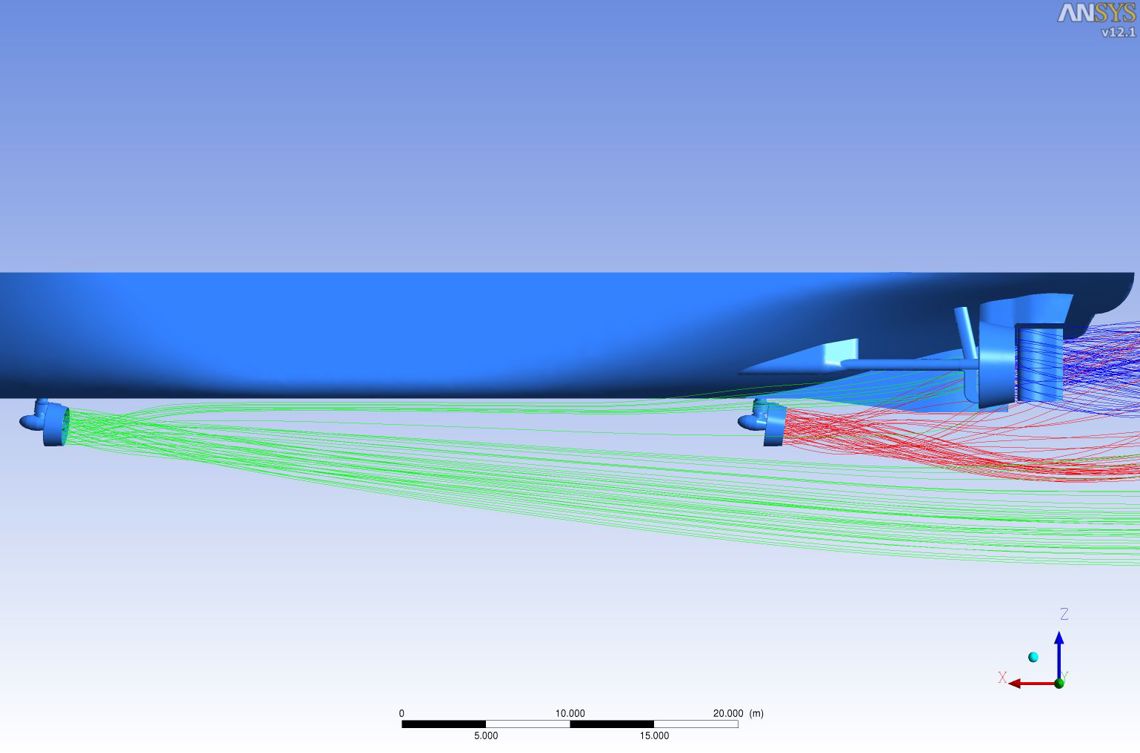
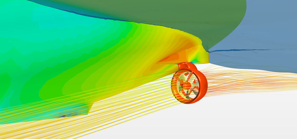
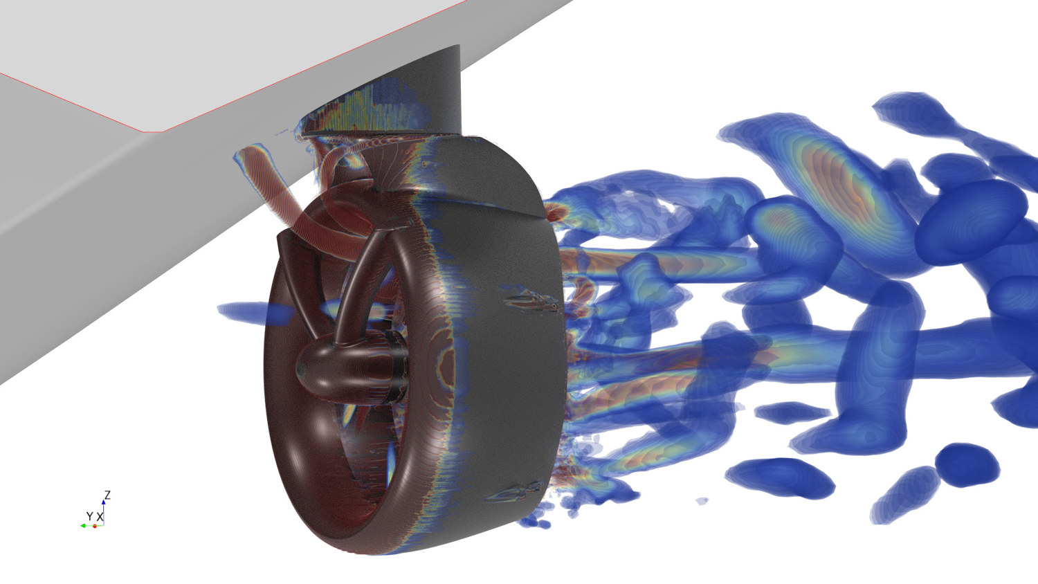
- Thruster-thruster interaction and/or thruster-hull interaction (e.g. nozzle tilt).
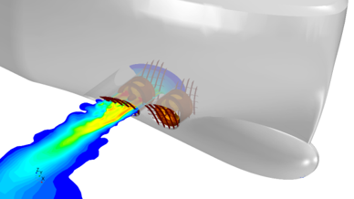
- Optimise tunnel thruster installation, tunnel inlet shape, positioning of tunnel thrusters and effect of tunnel grids.
- Identify propeller slipstream interaction with appendices.
- Static/dynamical loads for structural analyses.
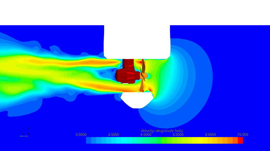
Fore Ship TT
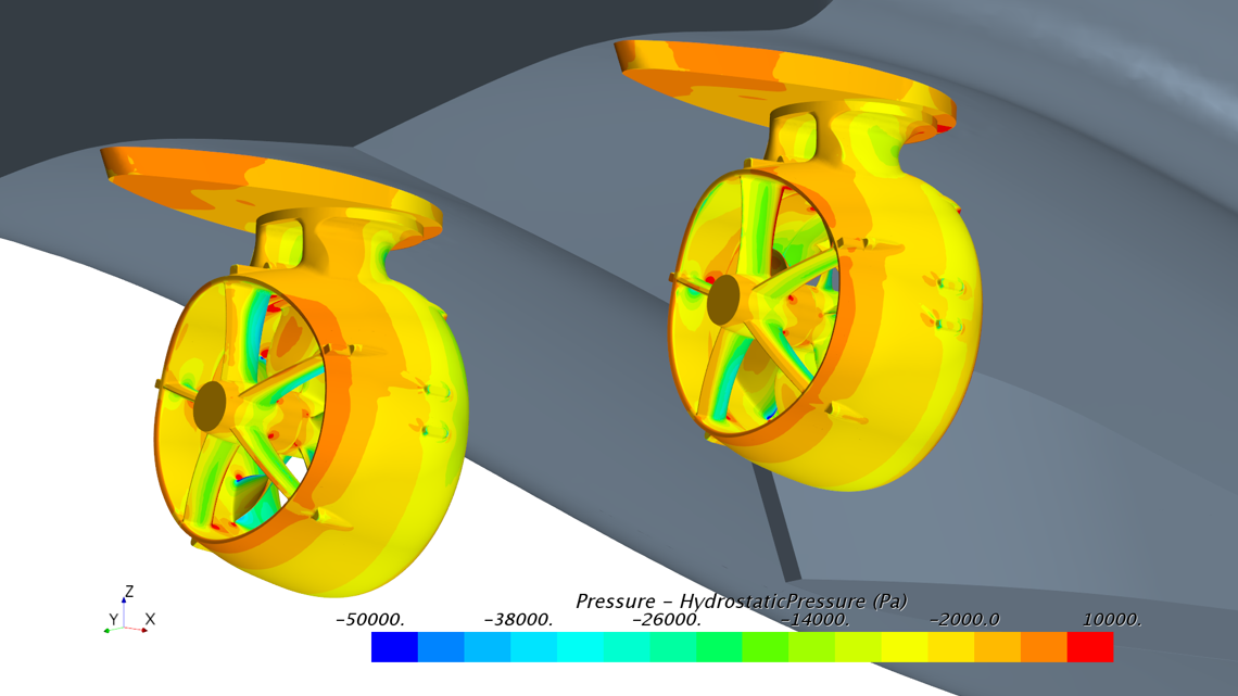
Hull SM Pressure - Hydrostatic Pressure