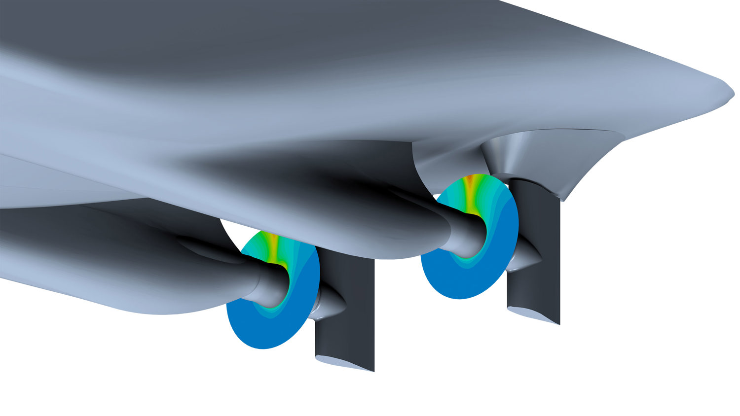
3D rendering of a ship’s hull fitted with twin propellers and rudders, with colour contours illustrating water flow pressure around the propeller hubs

Hull resistance and nominal wake

  • Bare hull simulation with the hull (and appendage) geometry but without propeller(s).
  • Prediction of hull resistance (PE) at certain ship speeds and drafts for hull lines optimisation.
  • Prediction of nominal wake field for optimisation of propeller inflow and input to propeller design.
  • The method calculates the free water surface and wave resistance using 2-phase (water and air) flow, steady state RANS and SST-kΩ turbulence model.
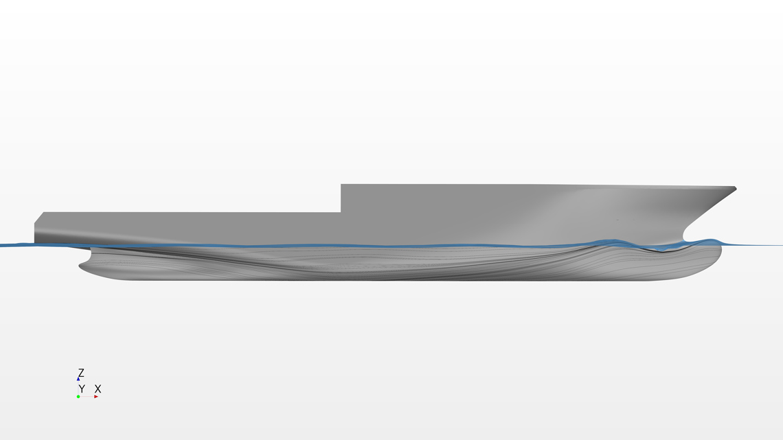
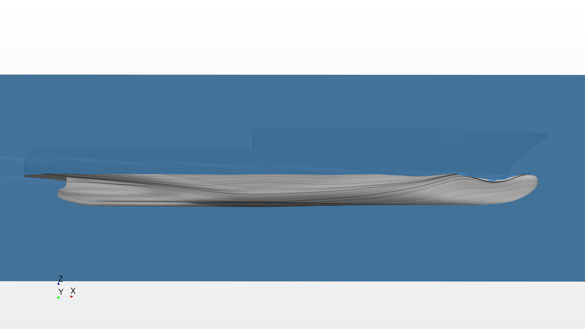
Side view of a ship hull with flow lines visualising water movement and wave patterns along the waterline

Hull Geometry - Side Oiltrace

Side view CFD visualisation of a ship hull in water, showing wave patterns and flow lines along the hull surface

Hull Geometry - Side Oiltrace 

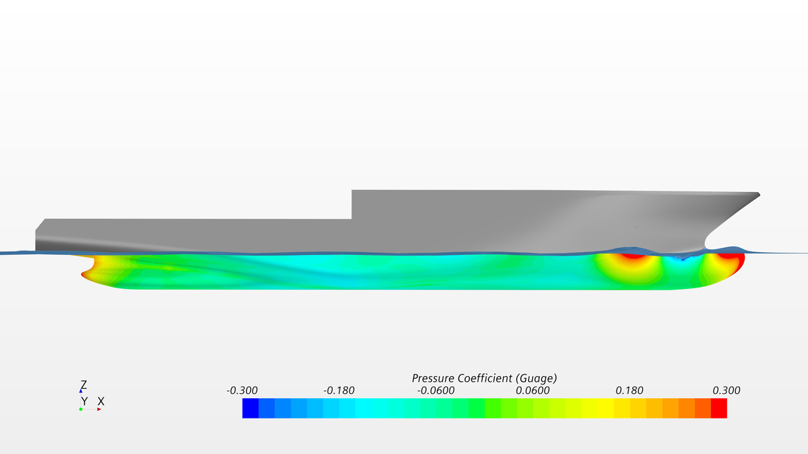
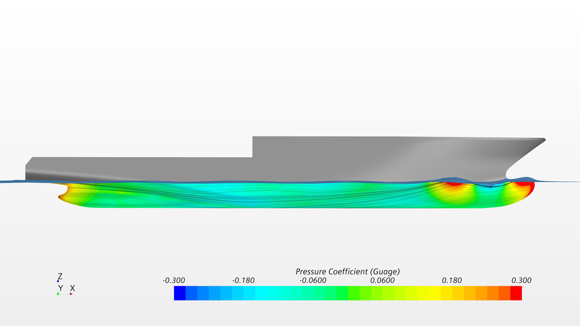
CFD visualisation of a ship hull with colour-coded pressure distribution and flow lines along the underwater surface

Hull Geometry - Side Pressure

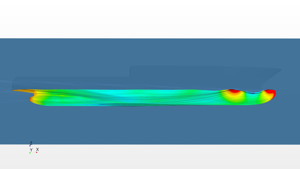
CFD side view of a ship hull with colour‑coded pressure distribution and flow lines highlighting areas of high and low pressure along the underwater hull

Hull Geometry - Side Pressure & Oiltrace
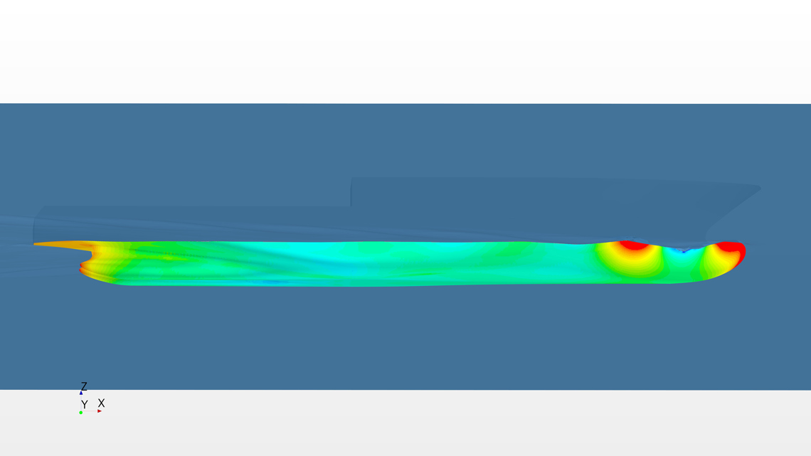
CFD side view of a ship hull with colour‑coded pressure distribution and flow lines highlighting areas of high and low pressure along the underwater hull

Hull Geometry - Side Pressure

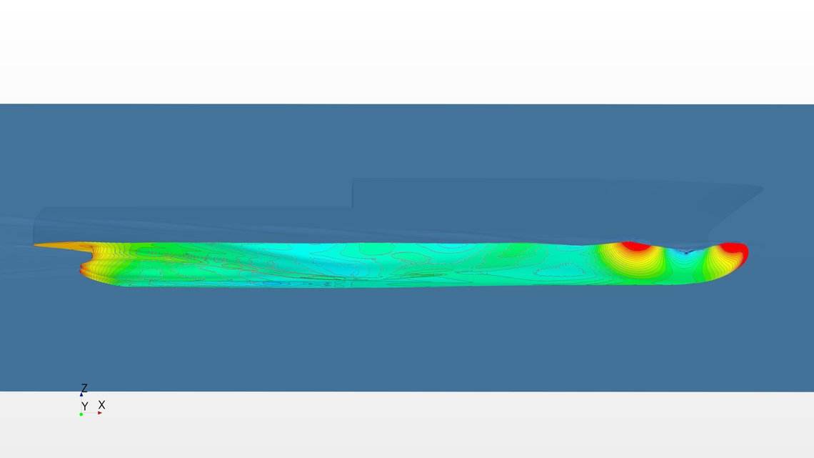
CFD side view of a ship hull with colour‑coded pressure distribution and flow lines highlighting areas of high and low pressure along the underwater hull

Hull Geometry - Side Pressure

CFD side view of a ship hull with colour‑coded pressure distribution and flow lines highlighting areas of high and low pressure along the underwater hull

Hull Geometry - Side Pressure & Oiltrace